
Keypads are used in all types of devices, including cell phones, fax machines, microwaves, ovens, door locks, etc. They’re practically everywhere. Tons of electronic devices use them for user input.
So knowing how to connect a keypad to a microcontroller such as an Arduino is very valuable for building many different types of commercial products.
At the end when all is connected properly and programmed, when a key is pressed, it show up at the Serial Monitor on your computer. Whenever you press a key, it shows up on the Serial Monitor. But for now, for simplicity purposes, we start at simply showing the key pressed on the computer.
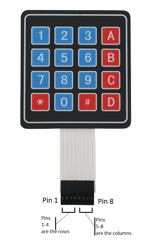
For this project, the type of keypad we will use is a matrix keypad. This is a keypad that follows an encoding scheme that allows it to have much less output pins than there are keys. For example, the matrix keypad we are using has 16 keys (0-9, A-D, *, #), yet only 8 output pins. With a linear keypad, there would have to be 17 output pins (one for each key and a ground pin) in order to work. The matrix encoding scheme allows for less output pins and thus much less connections that have to be made for the keypad to work. In this way, they are more efficient than linear keypads, being that they have less wiring.
Things Required
- Arduino UNO/Mega
- 4×4 Matrix Keypad
- Male to Male Header Pins
Know about the keypad
One of the most mysterious things about these keypads is that they usually come with no documentation, so a user is left to figure out the pin configuration for him or herself. However, we at this site, have figured it out.
With the keypad facing up so that the keys are up and facing you, from left to right, the 1st 4 pins are the row pins and the last 4 pins are the column pins.
Connections
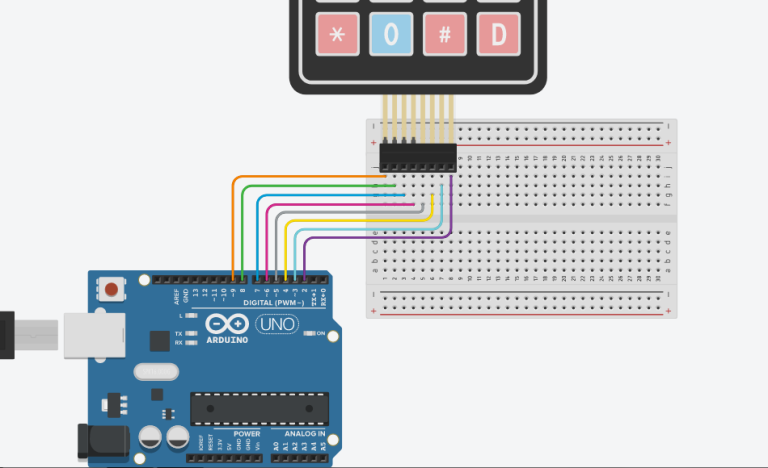
Connections of this project are straight and simple as shown above.
Code
#include <Keypad.h>
const byte numRows= 4; //number of rows on the keypad
const byte numCols= 4; //number of columns on the keypad
/*keymap defines the key pressed according to the row and columns just as appears on the keypad*/
char keymap[numRows][numCols]=
{
{‘1’, ‘2’, ‘3’, ‘A’},
{‘4’, ‘5’, ‘6’, ‘B’},
{‘7’, ‘8’, ‘9’, ‘C’},
{‘*’, ‘0’, ‘#’, ‘D’}
};
//Code that shows the the keypad connections to the arduino terminals
byte rowPins[numRows] = {9,8,7,6}; //Rows 0 to 3
byte colPins[numCols]= {5,4,3,2}; //Columns 0 to 3
//initializes an instance of the Keypad class
Keypad myKeypad= Keypad(makeKeymap(keymap), rowPins, colPins, numRows, numCols);
void setup()
{
Serial.begin(9600);
}
//If key is pressed, this key is stored in ‘keypressed’ variable
//If key is not equal to ‘NO_KEY’, then this key is printed out
//if count=17, then count is reset back to 0 (this means no key is pressed during the whole keypad scan process
void loop()
{
char keypressed = myKeypad.getKey();
if (keypressed != NO_KEY)
{
Serial.println(keypressed);
}
}
Now, upload the program and open the Serial Monitor. Then, press any button and you will be able to see the corresponding character of the screen.
For further help, you can got this link which will run the simulator made by me on Tinkercad.com for more easy understanding.
